
How To Check Repeater Working Performance?
Release Time:2022-10-25Source:JIELUODA INDUSTRY LIMITED
1. Nominal Maximum Linear Output Power Error Check
| Test items | GSM RF performance test |
| test child | Nominal Maximum Linear Output Power Test |
| Testing purposes | Verify the maximum output power of the digital repeater |
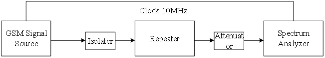
| Test instrument | GSM signal source, isolator, attenuator, spectrum analyzer |
| Preconditions | Connect the test instrument and the device under test according to Figure 1. |
| Test steps | 1. Turn off the uplink (measure the downlink output power) or turn off the downlink (measure the uplink output power); 2. Set the GSM signal source to the center frequency point within the operating frequency range, and generate a full-time slot GMSK signal ; 3. Set the digital repeater gain to the maximum gain; 4. Adjust the level of the GSM signal source until the ALC start control point, the carrier time slot power displayed on the spectrum analyzer should meet the tolerance range of the maximum output rated power declared by the manufacturer; 5. Note carrier time slot output level of the digital repeater ; |
| Test Data | 1. Recording equipment nominal maximum output power ; 2. Record carrier time slot output level and other information ; 3. Calculate the sum of the output levels of each carrier, that is the total output power of the digital repeater. |
| Expected outcome | The error of each carrier is within ±1.5dB ; The total output power error of the digital repeater is within ±1.5dB. |
2. Automatic Level Control (ALC)
| Test items | GSM RF performance test |
| Test child | Automatic Level Control (ALC) Testing |
| Testing purposes | Verify the automatic level control range of the digital repeater |
| Test instrument | GSM signal source, isolator, attenuator, spectrum analyzer |
| Preconditions | Connect the test instrument and the device under test according to Figure 1. |
| Test steps | 1. Turn off the uplink (measure the downlink output power) or turn off the downlink (measure the uplink output power); 2. Set the GSM signal source to the center frequency point within the operating frequency range, and generate a GMSK signal with a time slot of 50% (interval time slot) ; 3. Set the digital repeater gain to the maximum gain; 4. Adjust the level of the GSM signal source until the output power of the digital repeater is the nominal maximum output power test value; 5. Record digital repeater carrier time slot output power; 6. Increase the output signal level of the GSM signal source in steps of 1dB until it increases to 10dB, use a spectrum analyzer to test the output power of the digital repeater, starting from ALC until the maximum input power increases to 10dB, and record the digital direct the output power of the carrier time slot of the station; 7. The output signal level of the signal source in steps of 1dB until it increases to 20dB or to the maximum non-damaged input power. 8. Use a spectrum analyzer to test the carrier time slot output power of the digital repeater and record. |
| Test Data | Record the digital repeater carrier time slot output power. |
| Expected outcome | When the input signal level increases less than 10dB (including 10dB), the output power should be kept within ± 2.0 dB of the maximum output power; When the input signal level increases by more than 10dB (less than 20dB), the output power should be kept within ± 2.0 dB of the maximum output power or turned off. |
3. Maximum Gain and Error Test
| Test items | GSM RF performance test |
| Test child | Maximum Gain and Error Test |
| Testing purposes | Verify the maximum gain and error of the digital repeater |
| Test instrument | GSM signal source, isolator, attenuator, spectrum analyzer |
| Preconditions | Connect the test instrument and the device under test according to Figure 1. |
| Test steps | 1. Turn off the uplink (measure the downlink output power) or turn off the downlink (measure the uplink output power); 2. Set the GSM signal source to the center frequency within the working frequency range of the digital repeater, and generate a GMSK signal with a time slot of 50% (interval time slot); 3. Set the digital repeater gain to the maximum; 4. Sequentially adjust the level of the GSM signal source until the output power of the digital repeater is at the nominal maximum output power and back off by 5 dB 5. The maximum gain is the ratio of the output power to the input power of the digital repeater; 6. The maximum gain error is the difference between the measured maximum gain value and the rated gain value declared by the manufacturer, and the maximum deviation value is taken. |
| Test Data | Record the rated gain value declared by the manufacturer; Recording system digital repeater output power and input power; Calculate the maximum gain value and the maximum gain error. |
| Expected outcome | The nominal maximum gain of digital optical fiber repeater: within 55±3dB; The nominal maximum gain of the digital wireless repeater: within 95±3dB; |
4. Gain adjustment range
| Test items | GSM RF performance test |
| Test child | Gain Adjustment Range Test |
| Testing Purposes | Verify the gain adjustment range of the digital repeater |
| Test Instrument | GSM signal source, isolator, attenuator, spectrum analyzer |
| Preconditions | Connect the digital repeater according to Figure 1 ;Connect the test instrument and the device under test according to Figure 12 . |
| test steps | 1. Turn off the uplink (measure the downlink output power) or turn off the downlink (measure the uplink output power); 2. Set the GSM signal source to the center frequency within the working frequency range of the digital repeater, and generate a GMSK modulated signal with a time slot of 50% (interval time slot);Set the digital repeater gain to the maximum; 3. Adjust the level of the GSM signal source so that the output power of the digital repeater is the maximum output power declared by the manufacturer, back 1dB; 4. Measure the output power of the digital repeater at this time, and record the maximum gain as the ratio of the output power of the digital repeater to the input power at this time;Set the digital repeater gain to the minimum; 5. Measure the output power of the digital repeater at the RF output port at this time, and record the minimum gain as the ratio of the output power to the input power of the digital repeater at this time; 6. The difference between the maximum gain and the minimum gain is the gain adjustment range of the device. |
| Test Data | Record the nominal maximum output power of the digital repeater; Record the input power of the digital repeater during the test; Record the output power when the digital repeater gain is the maximum and minimum; The maximum gain is the ratio of the digital repeater output power to the input power; The minimum gain is the ratio of the output power to the input power of the digital repeater with the minimum system gain; The difference between the maximum gain and the minimum gain is the gain adjustment range of the device. |
| Expected outcome | Digital fiber repeater ≥20dB;Digital wireless repeater ≥30dB; |
5. Gain adjustment step size and error
| Test items | GSM RF Test |
| Test child | Gain adjustment step size and step size error test |
| Testing purposes | Verify the gain adjustment step size and step size error of the digital repeater |
| Test instrument | GSM signal source, isolator, attenuator, spectrum analyzer |
| Preconditions | Connect the digital repeater according to Figure 1 ;Connect the test instrument and the device under test according to Figure 12 . |
| Test steps | 1.Turn off the uplink (measure the downlink output power) or turn off the downlink (measure the uplink output power); 2. Set the GSM signal source to the center frequency within the working frequency range of the digital repeater, and generate a GMSK modulated signal with a time slot of 50% (interval time slot); 3. Set the digital repeater gain to the maximum; 4.Adjust the gain adjustment step size to reduce the gain of the digital repeater under test , measure and record the power level when the actual gain of the digital repeater under test decreases by each step length through the spectrum analyzer , until the gain is the minimum; 5.The actual gain adjustment step is the difference between each adjacent measured power level; 6.The step error is the difference between the declared gain adjustment step and the actual gain adjustment step; 7.Calculates the total gain adjustment accumulated error over the gain adjustment range . |
| Test Data | Record the power level when the actual gain of the system decreases by each step until the gain is the smallest; The actual gain adjustment step is the difference between each adjacent measured power level; The step error is the difference between the declared gain adjustment step and the actual gain adjustment step; Calculates the total gain adjustment accumulated error over the gain adjustment range . |
| Expected outcome | Gain adjustment step size≤1dB;The gain adjustment step error should not exceed ±1dB/step ; The total gain adjustment accumulated error within the gain adjustment range should be within ± 1dB . |
6. Error Vector Magnitude (EVM) and GMSK Modulation Accuracy
| Test items | GSM RF performance test |
| Test child | Vector Magnitude Error and GMSK Modulation Accuracy Test |
| Testing purposes | Verification of Vector Magnitude Error and GMSK Modulation Accuracy of Digital Repeater |
| Test instrument | GSM signal source, Isolator , Attenuator, spectrum analyzer |
| Preconditions | Connect the test instrument and the device under test as shown in Figure 1 |
| Test steps | 1. Turn off the uplink (measure the downlink output power) or turn off the downlink (measure the uplink output power); 2. Center the frequency of the digital repeater under test in turn; 3. Set the digital repeater gain to the maximum; 4. Set the output level of the signal source to the input level at the maximum output power; 5. Read the RMS EVM from the signal analyzer; 6. The output level of the signal source is increased by 10dB ; 7. Repeat step 5; 8. center frequency of the digital repeater under test in turn ; and set the output level of the signal source to the input level at the maximum output power; 9. Peak values of the phase error from the signal analyzer . 10. The output level of the signal source is increased by 10dB ; 11. Repeat step 9; |
| Test Data | Record EVM of GSM 8PSK signal ; Record the phase error RMS value and peak value of the GSM GMSK signal. |
| expected outcome | EVM ≤ 8% ( rms) ); Accuracy is no greater than 7°RMS and 28° peak. Bring the measured EVM into the formula EVM= where EVM S is the EVM of the signal waveform file itself. |
